Projekti za početnke
Arduino Blink
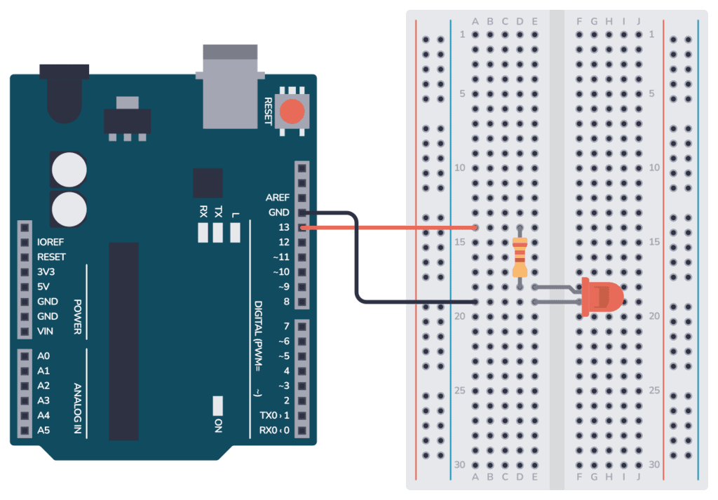
Jednostavan projekt za početnike koji koristi ugrađenu LED-icu na Arduino pločici za paljenje i gašenje svake sekunde.
Potrebni dijelovi:
- 1× Arduino UNO
- 1× LED (ako ne koristiš onu na pločici)
- 1× 220Ω otpornik
- Eksperimentalna pločica (opcionalno)
- Spojni kablovi
Kod:
// Blink primjer – pali i gasi LED svakih 1000ms (1 sekundu)

void setup() {
  pinMode(13, OUTPUT); // Postavi pin 13 kao izlaz
}

void loop() {
  digitalWrite(13, HIGH); // Uključi LED
  delay(1000);            // Čekaj 1 sekundu
  digitalWrite(13, LOW);  // Isključi LED
  delay(1000);            // Čekaj 1 sekundu
}
Objašnjenje koda:
setup()se izvršava jednom pri pokretanju i postavlja pin 13 kao izlaz.loop()se stalno ponavlja i upravlja LED-icom.
Rezultat:
Nakon učitavanja koda na Arduino, LED će treptati – svijetli jednu sekundu, pa se gasi jednu sekundu.
